Stereoscopic volume perception

In the past five years technology improvements made it possible to capture, modify and present technically good stereoscopic images. With devices able to capture high-resolution digital pictures and robust computer vision algorithms in postproduction, today we are able to produce high quality live action stereoscopic content – from a technical point of view.

This blog is an analytical engagement tackling a question living in the art domain of stereoscopic cinema: When does a ball look flat like a frisbee disk and when does it appear elongated like an egg?

To analyze volume perception we introduce a simple but powerful basic concept:

A 1x1x1 meter cube is used to virtually sweep through space away from the observer’s eyes to infinity. For each distance we measure the angles of width and depth on the observer’s retina, which causes the retinal disparity that elicits stereopsis. This ratio leads to a width to depth sweep through space (width to depth ratio vs. distance).

The same test setup is then duplicated. Instead of the eyes we have two cameras connected to a virtual cinema where our observer sits. Again we sweep our cube through space and measure the width and depth angles.

Having established this basic concept we then modify the parameters focal length and interaxial distance and see how they affect the »width to depth« ratio. During evaluation we find new dependencies between all parameters.

Moreover new measurement parameters will be presented, which simplify the usage of depth volume  in stereoscopic photography.

1. The basic concept of the cube

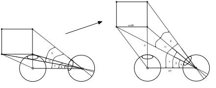
To explore stereoscopic volume perception we imagine a square cube that is aligned on the axis of the left eye (figure 1.1). The cube is moved from the left eyeball to infinity. Although this approach causes minor errors when the cube is very close, it simplifies the math for distances that are a multiple of the cube’s width. As there is just absolute parallax in one eye, the calculations only have to be done once. For latter equations we scale the cube down to improve our results.

One binocular depth cue for the observer is the disparity caused by the upper right and lower right corner of the cube. The retinal disparity can be measured as angle ∢δ.

To put this absolute angle in relation to something, we choose the retinal image caused by the width of the cube ∢ω. The ratio δ/ω then gives us an idea of the volume while the cube moves through space.

Figure 1.1

The theoretical concept of a cube sweeping through space. This sweep or chirp will give us a better understanding of how we perceive volume.

The following equations are used to compute plot 1.1.

  • pd = pupil or interocular distance of the observer            (65mm)
  • d = is the distance to the first surface of the cube
  • width = width of the cube (equal to the height and the depth of the cube)

, (1.1)

, (1.2)

, (1.3)

 , (1.4)

, (1.5)

 , (1.6)

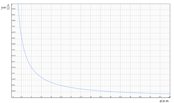
As we can see in plot 1.1, the depth of the cube decreases inverse to the distance to the observer.

Plot 1.1

The x-axis shows the distance of the cube to the eyeball. The y-axis is the ratio δ/ω. 

The cube has neither constant nor linear depth volume.

The cube’s width to depth ratio is affected by the distance to the observer.

A cube, being one meter away, has a greater depth to width ratio than the same cube that is several meters away. As there is a reciprocal relation to the distance, the volume significantly decreases in the first meters. Our cognitive system compensates for this inverse relation, so the perceived volume of »objects we know« stays constant. Objects must follow this curve to appear consistent while traveling through space. Similar behavior of the human cognitive process can be seen in the size consistency. Objects that come closer to the observer change their image size on the observer’s retina, while the perceived size stays constant.

2. The cube model in stereoscopic photography

The same setup is used for the next step. Only the observer’s eyes are replaced by two cameras.

Imagine the cameras are connected to a cinema theater, in which the observer sits. Again we examine the ratio »width to depth« on the observer’s retina.

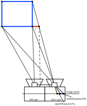
Figure 2.1

The eyes are replaced by two cameras in this setup.

2.1 Basic setup – ortho-stereoscopic image

For the first setup we use the following parameters:

Camera

  • Sensor width = 24mm (roughly a S35mm film back)
  • Sensor horizontal resolution = 2048 pixel
  • Focal length = 29mm
  • Interaxial distance = 65mm

Cinema

The observer has a angle of view of 45°. This is the arithmetic average of the theoretical sweet spot for 2048 pixel image resolution (36° – last row of a standard cinema) and the middle of a cinema (distance to the screen equals screen width (53°)). This seat is placed in the second half of a standard cinema and is therefore likely to represent a good average. The whole setup is screen size independent. For each screen size one pixel relative parallax will cause 1.5 minute of arc disparity in the observer’s eye.

After the projection of the three-dimensional cube onto a two dimensional image plane, the depth information lives as a relative parallax between the two images. The depth in the stereo image is the projection of the top right and bottom right corner (T: red line figure 2.1). In our setup the left camera captures no parallax, because it does not see the right top corner. All the absolute parallax is created in the right camera.

The two dimensional projection of the cube’s width on the camera’s image plane (in pixel) can be computed by equation 2.2. The two dimensional projection of the cube’s depth on the camera’s image plane (in pixel) can be computed by equation 2.3. The final ratio on the observer’s retina is shown in equation 2.4

  • T = real projection dimension of the cube’s depth in world space
  • hSensorPx = horizontal spatial image resolution of the sensor
  • sensorWidth = sensor width
  • widthProjectionPx = dimension of the cube’s width on the image sensor (in pixel)
  • depthProjectionPx = dimension of the cube’s depth on the image sensor (in pixel)

,(2.1)

,(2.2)

,(2.3)

, (2.4)

The ratio of relative parallax on the screen to disparity in the eye is not important, as it is canceled down by the quotient width/depth. The plot of this »width to depth« ratio results in exactly the same plot as plot 1.1. This way of capturing and screening is called ortho stereoscopy. The focal length (angle of view) at the capture is equal to the angle of view at the screening and moreover is the interaxial distance equal to the interocular distance.

2.2 Changing one parameter

If we choose a setup that corresponds to our human factors, we will get a natural reproduction of the depth volume. Anyway, in cinematographic work these camera parameters are rare. Limits like binocular rivalry or diplopia usually prohibit the use of these camera parameters, due to the mismatch of »camera to object« vs. »observers to screen« distance.

Let us analyze the effects of changing these parameters.

2.2.1 Changing the interaxial distance

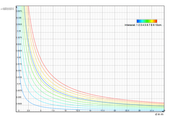
How does the interaxial distance affect volume perception? Plot 2.1 shows the resulting depth change.

Plot 2.1

The x-axis shows the cube’s distance to the camera rig. The y-axis shows the ratio depthProjectionPx/widthProjectionPx (equation 2.4). The colored lines represent the different interaxial distances of the camera rig. The dark blue curve in the middle represents the ortho stereoscopic volume

By increasing the interaxial distance the »depth to width« ratio gets bigger, and so the perceived volume. The depth volume is directly proportional to the interaxial distance. The mathematical expression is shown below. Equation 2.5 is the first fundamental depth volume expression 

, (2.5)

The y=1/x ratio of the curve is maintained, as visually seen in Plot 2.1 and mathematically described in equation 2.5. We can compare the interaxial change with a gain of the curve. Doubling up the interaxial distance will duplicate the depth volume.

2.2.2 Changing focal length

Does focal length behave in a similar way? Plot 2.2 shows different focal lengths with constant interaxial distances (65mm).

Plot 2.2

The x-axis shows the cube’s distance to the camera rig. The y-axis shows the ratio depthProjectionPx/widthProjectionPx (equation 2.4). The colored line  represent the different focal lengths of the camera rig. All of them fall on the same curve.

Surprisingly the depth plot was not altered by different focal lengths. The magnification change affects both, depthProjectionPx and widthProjectionPx in the same way (compare equation 2.2 and 2.3). As the depth plot is the quotient of »depth divided by width«, the focal length has been canceled down and does not affect the depth plot and therefore the depth volume.

However this result does not correspond to our daily experience in stereoscopic cinematography. It is well know that long lenses produce strongly reduced volume perception (cardboard effect). For this reason we have to examine focal length in greater detail.

2.3 Focal length and perspective

Point 2.2.2 is mathematically and analytically correct, but it does not represent a typical use of different focal lengths when framing a picture. Normally a change of focal length comes along with a change of distance to an object. We will have to take this change of distance into account, if we want to formulate a meaningful statement.

Example:

We frame a picture and our object of interest is 3 meters away. When we increase our focal length by a factor of 2 we also have to change the distance to 6 meters to achieve the same size of our object of interest within the picture. All other objects will have different sizes in both pictures. See figure 2.2

figure 2.2

The same scene captured with different focal lengths. In both pictures the white guitar on the left has the same image size. To achieve this the distance from camera to guitar was altered while changing the focal length. All other objects have different image sizes.

2.3.1 Natural focal length

Which focal length produces natural looking pictures? This focal length is determined by the angle of view of the observer in the cinema. If the angle of view at capture and the angle of view at the screening is equal, the picture will have a natural appearance. This does not necessarily have to match the normal focal length known in photography. If we have a smaller angle of view (greater focal length) the objects will appear closer as they were shot (telephoto) and vice versa.

So the appearance of distance changes; and we know (plot 1.1) that the distance to the object alters the volume significantly.

For our setup the natural focal length is 29mm (the focal length that matches the predefined observer’s angle of view ).

2.3.2 Object of interest and focal length compensation

We start with an example:

We have framed a picture with a focal length twice the natural length (≈ 60mm in our case) and the object of interest is 6 meters away. We could have achieved the same object size at 3 meters distance using a natural focal length (29mm). With 60mm focal length we are 3 meters farther away from the scene (all objects) than with natural focal length.

If we used a 60mm lens and our object of interest was  10 meter away, we would be 5 meter farther away from all objects. So the focal length compensation is influenced by the object of interest. Equation 2.6 shows this relation.

  • focalCompensate = focal compensation described above
  • distObjectOfIntend = distance to the object of interest
  • angleOf ViewCamera = camera’s angle of view
  • fieldOfViewObserver = observer’s angle of view

, (2.6)

3. Depth Budget

To evaluate a significant object of interest we briefly examine the concept of stereoscopic depth budget and screen plane. One possible stereoscopic strategy (among others) is to allow a certain amount of relative parallax, produced by the farthest object in the scene and the screen plane (= no absolute parallax). The stereographer defines a certain amount of depth budget (usually in pixel or as percentage of the horizontal image dimensions). This depth budget defines where the screen plane will be regarding the farthest object and the camera parameter (focal length and interaxial distance). Equation 3.1 shows the mathematical expression used to calculate the screen plane distance from the camera with the given parameters and a far-point at infinity.

, (3.1)

3.1 Interaxial distance and screen plane

For plot 3.1 we have chosen a depth budget of 25 pixel. At the intersection of the curves with the 25 pixel threshold we draw a straight line down the x-axis. This gives us the screen plane distance for each interaxial distance.

It gets bigger as the interaxial distance increases. There is a linear relation between screen plane and interaxial distance. If we double the interaxial distance we have twice the distance to the screen plane.

3.2 Focal length and screen plane

For plot 3.2 we have chosen the same depth budget of 25 pixel. Again we estimate the different screen plane distances for each focal length.

The screen plane distances get bigger as the focal length increases. There is the same linear relation between screen plane and focal length. If we double the focal length, we also have to double the distance to the screen plane.

Plot 3.1

The x-axis is the distance to the camera rig and the y-axis is the relative parallax in pixel. The colored lines represent depth plots for different interaxial distances.

Plot 3.2: The x-axis is the distance to the camera and the y-axis is the relative parallax in pixel. The colored lines represent depth plots for different focal lengths.

4 Changing focal length and staging – the density of roundness

We have discussed the relation between depth budget, screen plane, interaxial distance and focal length. Now we will use the strategy of screen plane to estimate a suitable object of interest. We define, that the object of interest is at screen plane distance. As we change focal length we will have to change the distance to the screen plane. For a large amount of todays stereoscopic cinema pictures the object of interest is near the screen plane. Again, this is just one possible style of stereoscopic-photography among others.

The approach will be as follows:

First we set the camera parameters (focal length and interaxial distance), then we calculate the screen plane distance. With this value we can then calculate the focal length compensation. Keeping this in mind we revisit at our depth plots again. We change the depth volume values according to the focal length compensation. So if we have a compensation of 5 meters, the new value for 5 meters now is the original 10 meter value. The new 10 meter value is the old 15 meter value et cetera. Graphically we shift the curve along the x-axis by the amount of the focal compensation, which is calculated by the screen plane distance.(equation 4.1)

, (4.1)

The x-axis is no longer the real distance [d] for all focal length. It just shows the same objects vertically aligned for all focal lengths.

Let’s say we have an actor 5 meters away in a ortho stereoscopic setup. He has an absolute volume of 0.013 (dashed blue line). The same actor will have an absolute volume of 0.0069 with a 50 mm lens (green curve) at same image size, because the distance to the camera rig has increased by the focal length compensation to 9.5 meters. So the actor appears with a strongly reduced volume perception, because he is 9.5 meters away from the camera rig, whereas the observer believes that the actor is 5 meters away.

This mismatch causes the unnatural distortion of stereoscopic depth perception (card-boarding).

Equation 4.2 shows how to calculate these mismatch caused by the unnatural focal length:

, (4.2)

Plot 4.1

The x-axis is the distance d from the cube to the camera rig only for the natural focal length (blue dashed curve). The y-axis shows the ratio depthProjectionPx/widthProjectionPx (equation 2.4). The colored lines represent different focal lengths of the camera rig.

Remember equation 2.6 for focal length compensation. Now we know why we cannot draw a general conclusion about focal length and volume perception. We can assert, that a bigger focal length compared to the natural focal length will produce a flattened depth perception and vice versa. But the extent is influenced by the object of interest.

The information provided in chapter 1-4 enables us to develop a lot of creative and artistic concepts and to formulate some key parameters to describe depth volume within a scene.

5. Stereoscopic volume parameters

This chapter tries to provide some useful and practical parameters in order to sufficiently describe depth volume and depth volume perception for each point within a scene. The following three parameters offer valuable information to judge stereoscopic volume perception:

  • specific volume
  • volume gain
  • volume density

5.1 Specific volume 

A suggestion for a specific volume parameter is a slight modification of the depth volume in equation 2.6.

, (5.1)

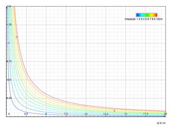
Plot 5.1

The x-axis is the distance d from the cube to the camera rig. The y-axis shows the specific volume (equation 5.1). The colored lines represent different interaxial distances.

By normalizing the interaxial distance (equation 5.1) the numbers for the depth volume become more handy. For an ortho stereoscopic setup the volume is simply 1 divided by the distance. The specific volume of an object which is 3 meters away is 1/3. If we now decrease the interaxial distance to 22 mm (≈ a third), we will also decrease the volume by this amount ≈ 1/9.

The volume for each individual point can easily be  calculated. This is the absolute value from which all  others are derivated. It is only affected by the interaxial distance and the distance to the camera rig.

5.2 Volume gain

The volume gain shows the ratio between the specific volume in the scene and the specific volume in the same scene with an ortho stereoscopic setup – compared to the object of interest. If the focal length is natural, the volume gain will be the  same for all points in space (the curve becomes a line parallel to the x-axis). Values below 1 indicate an overall shallower depth. Values above 1 indicate an overall greater depth. However, a »cinematic picture« might have a volume gain below 1 for most shots. The more important thing is the consistency of gain. If a long lens is used, then the volume gain will be smaller for near objects. That means that close objects have a more reduced specific volume than objects that are farther away. If the focal length is smaller than the natural focal length, the volume gain is greater for near objects and shallower for the distant ones. Equation 5.2 shows the mathematical relation.

, (5.2)

Plot 5.2

The x-axis is the distance d from the cube to the camera rig. The y-axis shows the volume Gain (equation 5.2). The colored lines represent different focal length at fixed interaxial distance.

The volume gain gives us a good idea of the scene. It tells us the depth volume amplification caused by the interaxial distance and the focal length/staging. When the curve is a horizontal line we have chosen the natural focal length and therefore no unnatural depth volume will be perceived.

Anyway, when you look at a specific value for one specific object (without knowing the curve) the volume gain alone does not tell whether there is a natural or an unnatural gain.

It might therefore be useful to have an indicator just for the mismatch caused by the focal length/staging.

5.3 Volume density

The volume density is the normalized mismatch described in chapter 4. A value below 1 indicates a reduced depth volume perception (card-boarding) and a value above 1 will elongate the volume. The volume density does not account for the change of volume gain caused by a change of interaxial distance.

Equation 5.3 shows the normalization:

, (5.3)

Plot 5.3

The x-axis is the distance d from the cube to the camera rig. The y-axis shows the volume density (equation 5.2). The colored lines represent different focal length at fixed interaxial distance.

A natural focal length will therefore produce the value 1 for all objects in the scene. The distance to the object of interest might change as well as the focal compensation. So the interaxial distance might affect the volume density indirectly.

6. Other depth cues

We should keep in mind, that changing the camera parameters will also affect other depth cues. As the final cognitive depth evaluation is a sum of all perceptual inputs, we should have a brief qualitative look at other depth cues.

Table 5.1 shows how depth cues are altered by interaxial distance and »focal length/staging«

Table 5.1

Qualitative enumeration of some depth cues and how they are affected by the creative camera parameters.

When looking at table 5.1 the importance of focal length gets even more evident. A lot of depth cues are strongly affected by the change of »focal length and staging«. Especially monocular depth cues can only be  modified with the lens. Monocular depth cues and their perception are strongly cognitive. It is hard to develop a quantitative statement with an analytical approach. More empiric research has to be done in this area.

7. Conclusion 

The simple equations 5.1, 5.2 and 5.3 describe the complex interlock of interaxial distance, focal length and staging. Only if each and every of these parameters is available to the stereoscopic creative staff perfection in stereoscopic photography can be achieved.

The most dramatic effect is caused by the focal length because it can distort the volume perception in an unnatural way. Who ever chooses the lens on a stereoscopic show must be aware of its behavior. The lens, when chosen wisely, provides the best opportunity for an creative engagement with stereoscopic photography.

Of similar importance in a »stereoscopic picture« is the staging of action and camera within space. The alignment of »things« is as important as the focal length. Again this is an opportunity for creative engagement with depth and volume.

With the three parameters specific volume, volume gain and volume density the artist has a model that can assist in making creative decisions and make stereoscopic photography more transparent in terms of volume perception.

A color-driven way of thinking about stereoscopic volume capture could be:

Staging is like lightning your scene,

focal length is your contrast correction,

interaxial is your gain correction ,

…and you can hardly alter them in post…

References:

  • Jules, Bela: Foundation of Cyclopean Perception. MIT Press. London 2006.
  • Kuhn, Gerhard: Stereofotografie und Raumbildprojektion. Vfv Verlag. Gilching 1999.
  • Siragusano, Daniele. Target Screensize for stereoscopic feature film. SMPTE Paper 2010.
  • Swartz, S., Charles: Understanding Digital Cinema. Focal Press. Oxford 2005.
  • Tauer, Holger. Stereo 3D Grundlagen, Technik und Bildgestaltung. Schiele Schön. Berlin 2010.
Master Screensize

The following blog is a paper I have written 2010 for the 2010 SMPTE International Conference on Stereoscopic 3D for Media and Entertainment

Abstract. For stereoscopic pictures the geometric dimension on set and the geometric situation at the screening interact with each other. The combination of both produces the final depth perception at the observer. The screen size is believed to be a central variable in the process of creating a stereoscopic picture. The information of the screen size must be known during shooting. But different screen sizes at different theaters raise the question: What is the target screen size for stereoscopic feature film? This paper tries to examine this question.

Keywords. Screen size, target screen size, disparity, relative parallax, absolute parallax, divergence, binocular rivalry, panum’s fusion area,

Introduction

Stereoscopic feature film entails new challenges to every part of filmmaking. Preproduction, production and postproduction are confronted with new questions. Postproduction facilities, for example, have to implement new processes to modify stereoscopic characteristics, like »stereo refinement« and »depth grading«.

But the big difference between stereoscopic and traditional »planar« feature film is that the stereoscopic process chain must be regarded as a whole, from the trigonometric dimensions on set all the way to the geometrical situation when screening the final product.

Figure 1. Stereoscopic production chain must be seen as one process.

Most concerns in stereo-photography are made about how to choose the target screen size. Stereographers need this value (target screen size or projection magnification) to feed in their calculators – but why?

Equation 1 shows one fundamental equation for stereoscopic picture (approximation). [KUHN1999]

  • s = screen plain
  • IA = inter-axial distance
  • f = focal length
  • p = max. absolute parallax (on the image sensor)

Eq 1: 

Lets examine p:

The max. absolute parallax p is limited by the “prohibition of divergence”. [KUHN1999]  The absolute parallax p on the screen must not be bigger than inter inter pupillary distance PD. Therefore a magnification m must be known (See equation 2).

Eq 2:

The magnification m is the ratio of image sensor size c to screen size C (see equation 3):

Eq 3:

The stereographer has control over all variables (distance to the screen plane, focal length, interaxial distance, image sensor size) except from the screen size.

What happens if the stereoscopic content is shown on different screen sizes?

When a stereoscopic movie is made for a five meter screen for example, the maximum absolute parallax may be equal to the distance of the eyes (≈ 6.3 cm). If the same feature film is projected on a 10 meter screen everything is doubled. So the maximum parallax is 12.6 cm. This cause the eyes to »toe out« or diverge when they try to fixate this point. Too much divergence is bad because it cause eyestrain and headache. If on the other hand the screen size is diminished – the parallax is diminished as well and will maybe cause reduction of the depth effect.

But it is not practical and not possible to shoot a stereoscopic movie to fit for all screen sizes. So what should be the best trade off for a target screen size and are all these concerns necessary?

There are no real statements about the optimal screen size in literature. A well-known consideration is to go for 12 meter screen width. [Lipt2010] But is this practical?

In this chapter the reader will find an analytical approach to find the optimal target screen size for cinema projection. On the way to the answer the reader will find an alternative approach to this subject.

1 Preconditions

Some preconditions must be defined to fixate some of the variables.

1.1 Viewing distance

Regulation communities like THX and SMPTE have the same motivation for defining the optimal distance for a theatrical planar screening. The spatial resolution of one eye is crucial. At the optimal distance the eye can just not resolve the resolution or the raster of an image. For a normal person with 100% (20/20 acuity) in a typical screening environment (photopic vision) the resolution of one eye is about one arc minute per cycle. [POYN2007]In context to spatial resolution the viewing distance or angle depends on the screen width and the spatial resolution of the image. The viewing angle in degree is described by equation 4. The resulting distance is described in equation 5. The optimal distance will be called »sweet-spot«.

Eq 4:

Eq 5: 

The nearest distance for this assumption is the first row of a typical cinema. The typical first row is at 0.8 of the screen height for a cinema-scope presentation. [SWAR2005]  The distance is computed by the equation 6. Another »bad« seat is the distance where one pixel covers two arc minutes of the observer. This »bad-spot« is closer than the screen width and describes a non-optimal seat in the first half of a theatre. The distance is computed by the equation 7.

Eq 6:

Eq 7:

Every distance greater than the sweet-spot is not important for this scope, because increasing the distance will diminish errors. The »vivid plastic impression« or »roundness« is enhanced or exaggerated if the audience have greater distance to the screen than the theoretical sweet-spot.

In figure 2 all defined spots are sketched in a typical theater room for 2048 pixel spatial horizontal image resolution. Notice, that the theoretical sweet-spot is almost at the last row. This fact pose the question if 2048 pixel image resolution if enough for digital cinema (planar and stereo). At CinePostproduction a more practical sweet-spot was defined which elicit a theoretical resolution of 2600 pixel.

Figure 2. The predefined spots sketched in a typical cinema. [SWAR2005 p.230]

1.2 Screen range

A limiting factor for stereoscopic projection is luminance. Half of the light output goes to the left eye and half goes to the right eye. After that 70% of the remaining light is consumed by the optical elements like modulator (3d system) and analyzer (glasses). Another portion is lost due to time multiplex, which is used for a one-projector setup.

The result is, that 15% to 30% of the light output arrives at the observer. This fact limits the screen size. The current practice at cinemas is a peak white luminance is in the range from 3.5 to 5.5 ft-L at 25 meter maximum screen width.

The lower white point luminance around 5 ft-L compare to 14,8 ft-L for planar cinema, influence the human color perception. It is important to color grade the feature under these circumstances and to perform a match grade for planar, and therefore brighter releases.

For this scope the range of screen widths will be 4 meters for very small theaters to 25 meters for big screens.

1.3 Divergence

»The amount of divergence that a person can tolerate will depend on each individual, but a normal value for maximum divergence, when viewing a distant object like a movie screen, is about 4 degrees. Since this is a maximum value, it might fatigue the eyes, so a more comfortable value would be about half of this amount, or about 2 degrees.« [SALM2010]

To provide additional headroom for smaller inter pupillary distances the value is reduced to 1° in some calculation.

1.4 Parallax and disparity

To take the result from visual science into account it is necessary to define the relation between parallax on the screen and the disparity on the retina. Disparity in degree is defined as the angle difference between two points in space (∡L and ∡R). The same disparity can be measured at the difference between angle α and β – see figure 3. [SALM2010]

Figure 3. The relation disparity in the eye and relative parallax on screen is a triangular relationship

To compute alpha or any other angle of a given point via its projections Al and Ar, the triangle ∆ El-Al-Al’ can be used. The distance El-Al’ is the sum of PD/2 and the screen-parallax (Al-Ar)/2. (PD is the inter pupillary distance) The distance Al-Al’ is d = distance to the screen. Equation 8 and 9 shows the final equation to calculate one angle.

Eq 8:

Eq 9:

  • apix = screen parallax in pixel
  • a = screen parallax
  • r = spatial horizontal image resolution
  • w = screen width
  • d = distance to the screen
  • pd = interpupillary distance
  • alpha = angle of one point

The minus operant in (pd/2-a/2) is chosen instead of the plus operant, because a crossed disparity (negative parallax) will generate negative parallax values by definition.

The disparity η is the difference between two angles. Equation 10 and 11 show the final Equations to calculate η.

Eq 10:

Eq 11:

  • bpix = screen parallax of the second point in pixel
  • b = screen parallax of the second point in meter or centimeter
  • η = the disparity between point A and B in degree

So disparity is the difference between two point-pairs on the screen. It is the difference between two parallaxes or the relative parallax.

Disparity refers to the eye (intrinsic)

Relative parallax refers to the screen (extrinsic)

An example:

A foreground object appears in front of the screen and has the parallax -10 px (scrub in figure 4). A background object far behind in space has the parallax +24 px (tree in figure 4). So the resulting relative parallax for the image is 34 px or ≈ 34 arc minute disparity for the sweet-spot position – see figure 4.

Figure 4. A captured scene with perceived objects and their projections on the screen.

Note, that the ratio relative parallax to disparity is screen size independent, because the distance to the screen is constrained by the screen width.

The ratio relative parallax (in pixel) to disparity (in minute of arc) is:

  • 1:1 for sweet-spot
  • 1:2 for bad-spot
  • 1:3,3 first row
  • Viewing distance is a function of screen width
  • Screen width range is 4-25 meters
  • The allowed divergence amount is 1° to 2°
  • The relation between relative parallax and disparity is angular and stays constant for every screen width

Summary of pre-conditions

  • Viewing distance is a function of screen width
  • Screen width range is 4-25 meters
  • The allowed divergence amount is 1° to 2°
  • The relation between relative parallax and disparity is angular and stays constant for every screen widt

2 Calculations

Some single aspects about stereoscopic projection will be contemplated. At the end al respective conclusions will be summarized and a final statement may be formulate. All calculations refer to 2048 pixels spatial horizontal image resolution.

2.1 Maximum parallax without divergence

Plot 1 shows the screen width (in centimeter) vs. the interocular parallax (in pixel). For this parallax the eyes look parallel, greater parallax cause divergence.

Plot 1. Shows the relation between screen size and interocular parallax.

The bigger the screen the less pixel are available until the interocular-parallax is reached, because the pixel dimension on the screen gets bigger.

Note, that the ratio »distance – screen width« cause the ratio »relative parallax – disparity« to stay constant for every screen width. In other words: one pixel disparity is the same angular disparity for every screen width, for a constant viewing distance relations.

Some statements can be justified:

  • The bigger the screen, the smaller the maximal parallax and therefore the smaller the relative parallax.
  • Smaller screen sizes cannot be easily adopted to bigger screens (compare 40 px at 3 meters and 6 px at 20meters)
  • Reviewing screens smaller than 5 meters are inappropriate. After 7 meters the function might be smooth enough for practical purpose.

On the one side a bigger maximal parallax may give more flexibility in shooting a stereoscopic feature, but on the other side it is less compatible for changes in screen size. To determine a good trade off for parallax budget and compatibility more aspects have to be taken into account.

2.2 Parallax and divergence

The x-axis of plot 2 is absolute parallax in pixel. The y-axis is distance to the screen. The straight colored lines describe the relation between parallax and the distance for a given screen width, where divergence is exactly 1 degree. The three curves shows the three predefined spots in the cinema (first row, bad-spot, sweet-spot).

Plot 2. Shows the relation between distance to the screen and absolute parallax, where divergence is 1°.

The three curves aspire a fixed value for infinite screen width:

  • first row: 11.97 px
  • bad-spot: 26.36 px
  • sweet-spot: 58.22 px

Some statements can be justified:

  • There is a broad tolerance between interocular-parallax and comfortable divergence.
  • A parallax of 12 pixel will never cause any uncomfortable divergence for any screen size
  • A parallax of 17 pixel will not cause uncomfortable divergence for todays screening situation.
  • A parallax of 31 pixel will not cause uncomfortable divergence for the most seats in a cinema.

Plot 3 is analog to plot 2. The plot shows the distance to the screen for 2° divergence.


Plot 3. Shows the relation between distance to the screen and absolute parallax, where divergence is 2°.

The three distance curves again aspire a fixed value for infinite screen width:

  • first row: 23.93 px
  • bad-spot: 52.75 px
  • sweet-spot: 116.47 px

Some statements can be justified:

  •  A parallax of 24 pixel will never cause a divergence greater than 2° for any screen size.
  •  A parallax of 29 pixel will not cause a divergence greater than 2° for today’s screening situation.
  •  A parallax of 52 pixel will not cause a divergence greater than 2° for the most seats in a cinema.

Divergence only occurs when a point with a parallax greater than the inter pupillary distance is actually fixated. So a stereoscopic sequence may have greater parallax values in a frame, if the attention (and therefore fixation) of the observer is on a closer object, like a foreground object. So divergence might not be a limiting factor for stereoscopic cinema at all?

A limiting factor that is more severe is binocular rivalry or the boundaries of patent stereopsis (comfortable and quantitative stereopsis). Stereopsis is the sense of depth perception. Is there a need for a depth budget of 50 px ≈ 50 min of arc disparity and more?

2.3 What disparity is appropriate

There are some values given by physiologic science that can be adopted for stereoscopic cinema.

Panum`s fusion area is the disparity range a human perceives an object as a single sharp object. Its range is about 6 arc minute around the fixation point. [JULE2006] For stereoscopic screening under the pre-conditions mentioned above this is a relative parallax of 6 px at sweet-spot and 3px at bad-spot and 1.8px and first row.

A form of binocular rivalry (eye suppression) is the phenomenon between foreground and background where eyestrain occurs. Binocular rivalry is the antithesis to fusion. [HERS2000]     It happens, when the difference (disparity) between the two images is too big. It starts more or less at 25 arc minute disparity. That is 25 Px relative parallax for sweet-spot, 12,5Px for bad-spot and 7,6 Px for first row. After this value the perceived depth perception decrees and start to suppress.

Plot 4 shows the relation binocular disparity in minutes of arc to the perceived depth. The blue and green areas are the comfortable ones (patent stereopsis). But only the green area can be used in actual cinema screening at a resolution of 2048 pixel at sweet-spot or greater distance.

Plot 4. Shows the relation between binocular disparity and perceived depth. [HERS2000 p.56]

An image can have greater values of disparity and still looking ok, but as a base these clues can be consulted. Characteristics that alter the start of binocular rivalry are for example image size, temporal and spatial frequencies, eccentricity, illumination, vergence mechanism and practice. Remember, the mentioned disparity is the difference between two parallax values.

  • Relative parallax is more crucial than absolute parallax.
  • Is the classical cinema architectural situation suitable for stereoscopic movies? (Compare first row with sweet-spot in terms of disparity)
  • Stereoscopic cinema needs more horizontal spatial resolution (blue part of plot 4)

3 Conclusion for target screen size

First all the statements are summarized

  • For every screen the relation relative parallax (in pixel) to disparity (in min of arc) is 1:1 for »sweet-spot«, 1:2 for »bad-spot« and 1:3.3 for »first row« due to the pre-condition of distance.
  • The bigger the screen, the smaller the maximal parallax and therefore the smaller the relative parallax when composing for no divergence.
  • Smaller screen sizes can not be easily adopted to bigger screens (compare 40 px at 3 meters and 6 px at 20meters)
  • Reviewing screens smaller than 5 meters are inappropriate
  • There is a broad tolerance between interocular-parallax and comfortable divergence.
  • A parallax of 12 pixel will never cause any uncomfortable divergence for any screen size
  • A parallax of 17 pixel will not cause uncomfortable divergence for today’s screening situation.
  • A parallax of 31 pixel will not cause uncomfortable divergence for the most seats in a cinema.
  • A parallax of 24 pixel will never cause a divergence greater than 2° for any screen size.
  • A parallax of 29 pixel will not cause a divergence greater than 2° for today’s screening situation.
  • A parallax of 52 pixel will not cause a divergence greater than 2° for the most seats in a cinema.
  • Panum`s fusion area is 6 min of arc around the fixation point. For stereoscopic screening under the pre-conditions mentioned above this is a disparity of 6px at sweet-spot.
  • Binocular rivalry more or less starts at 25 arc minute.
  • Relative parallax is more crucial than absolute parallax.
  • Is the classical cinema architectural situation suitable for stereoscopic movies? (Compare first row with sweet-spot in terms of disparity)
  • Stereoscopic cinema needs more spatial horizontal resolution (blue are of plot 4)

3.1 Consideration for absolute parallax

The maximal absolute parallax can be enlarged by divergence considerations. For more flexibility the range of interocular-parallax can be expand to some extend (see plot 2 and 3). Note, that the most stereoscopic calculators calculate parallax for no divergence. So a stereographer should discern between mathematical target screen size (producing no divergence), desired absolute parallax and review screen size. For judging depth perception a screen equal or larger then 7 meters is practical (smooth region of plot 1).

3.2 Consideration for relative parallax

For depth perception only relative parallax is relevant. With the 1:1 relation for relative parallax and disparity it is feasible to stay within the ranges known from physiological science. The 1:1 relation is only true for the sweet-spot. For seats with greater distance the angles become smaller and won’t cause any error. For seats closer to the sweet-spot the angles and so the disparity gets greater. It is a trade off between compatibility and depth budget. The relative parallax is the limiting factor in practical approach. The first third of a theater is a problem zone because the disparity difference between first row and sweet-spot is hugh (compare 7.6 Px to 25 Px). Unfortunately a content creator (stereographer, Dop, Director) must pick a position in the theater to master for. Seats closer to the screen will have less depth and more disparity. To master for the first row is unpractical, because a lot of depth budget is lost. To master for the sweat-spot is unpractical as well, because most of the seats in a theater will have a smaller distance to the screen.

The last and most important guideline is human cognition. It is the job of the stereographer and the stereo-grader to judge every shot in a real time big screen environment and correct both the absolute and relative parallax if it is needed. This is not done, by simply shifting the images horizontal. A horizontal Image translation will not change the relative parallax or disparity!

Final Conclusion

The master-screen size question is not answered with a single value, but a range is provided, giving freedom for creative approach. There are two target screen sizes:

  •  A theoretical screen size that is used to calculate the desired disparity (shot dependent, can vary from shot to shot)
  •  A practical screen size to judge depth perception of stereoscopic content ( >7 meter).

What happen when a stereoscopic content for cinema is watched on small screen sizes like Consumer Displays or Laptops? If the choice of distance is calculate the same, the angular proportion stay constant (1 px relative parallax ≈ 1 arc minute disparity). Normally the ratio distance to the display is greater compare to cinema. Additionally in such small distances (within grasping reach) other physiological effects come into account, like change in »size constancy«. Stereoscopic feature film may be reviewed and »HIT- modified« for small screen deliveries in future, as it is modified nowadays in terms of color for HDTV Releases.

Stereoscopic film has no problem with different screen sizes but with different viewing angles.

Books

[HERS2000] Hershenson, Maurice: Visual Space perception, A Primer. MIT Press. Cambridge 2000.

[JULE2006] Jules, Bela: Foundation of Cyclopean Perception. MIT Press. London 2006.

[KUHN1999] Kuhn, Gerhard: Stereofotografie und Raumbildprojektion. Vfv Verlag. Gilching 1999.

[POYN2007] Poynton, Charles: Digital Video and HDTV, Algorithms and Interfaces. Morgen Kaufmann Publishers, San Francisco 2007.

[SWAR2005] Swartz, S., Charles: Understanding Digital Cinema. Focal Press. Oxford 2005.

Internet

[Lipt2010] Lipton, Lenny: What to do about the big screen <http://lennylipton.wordpress.com /2008/04/10/what-to-do-about-the-big-screen/> (16.02.2010)

Lecture Notes

[SALM2010] Salmon, Thomas O. OD, PhD, FAAO: Vision Science 3 -Binocular Vision Module, Lecture – Stereopsis. Lecture Notes.

depth warping caused by toe in cameras

depth warping caused by toe in cameras

This is my first blog on this platform. Therefore some words about my intention. I don´t want to add another source for stereoscopic basics and fundamentals. Topics I will post are advanced clues and thoughts (in a short way) I didn`t found in the standard stereo literature. Maybe I won`t post that much, but it will be »stereo in depth«. I hope you will post some comments and let me know what you think.

depth warping caused by toe in cameras

there are a lot of pros and contra for and against the use of toe-in camera rigs. For example we all know the keystone distortion problem and the solution by epipolar geometry.

This blog will not be another boring enumaration of facts, but will add a point to that list, I am missing every time I stumble over such an article.  Yei-Yu Yeh and Lenny Lipton first formulated this coherence. And sorry Toe-In fans it is against toe-in:

By miming the convergence of the eyes, toe in cameras also mime the horopter characteristics. All points lying on the horopter will be captured with no parallax. When displaying this sterescopic image onto a flat surface like a theater screen, these point (first laying on a circle) will be mapped onto a flat surface, causing a geometrical distortion of the scene.

The figure below sketches this depth distorition:

The first (above) assembling shows a toe in configuration, the second a parallel. Note that the HIT (horizontal image translation) for the parallel assembling is sketched by the moved image planes within the camera.

Imaging the situation of three talking heads parallel to the camera (bubble 1 to 3 in the figure). If captured with toe in, Person 2 and 3 would appear behind the screen.

Lenny Lipton discribed this fact as a zero parallax locus and Yei-Yu Yeh as a perspective projection of a semicylindrical stereo window mapped on to a flat surface (screen).

What do you think?